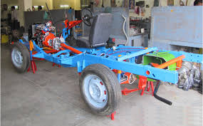
Car Chassis Rear Wheel Drive Actual Cut Section – Motorised
4 Stroke 4 Cylinder Petrol Engine With Clutch, Gear Box, Propeller Shaft, & Rear Axle Assembly With Differential Gear
The chassis of the four stroke four cylinder engine cut section model. The cut section model is constructed such that all the following systems can be demonstrated in working conditions.
ENGINE
Maximum parts and accessories of an engine like cylinders, cylinder head, inlet and Exhaust manifolds, FIP, injectors, self-starter, alternator, water pump, radiator, etc., are sectioned to show the internal constructional details. The complete sectioned model is coupled with FHP 220/230V A.C single phase motor through a Reduction drive unit.
TRANSMISSION SYSTEM :
This system consists of a Clutch and four speed gearbox assembly, the casing of which is suitably cut to demonstrate its operation. The gearbox is coupled to Differential gear box with propeller shaft and the different coupling used for this transmission can be demonstrated. The Differential gear box is also cut so as to clearly to demonstrate its complete operating principle. The gear shifting including the forward and reverse gear operation can be clearly shown. The speed variation and the rotation of the Differential gear box can be seen while gear shifting. By running the motor connected to the engine assembly the entire system with gear box, rear axle etc. can be demonstrated in running.
FUEL SYSTEM : The Fuel tank is cut to expose the mounting of the level sensor and the position of Fuel section. The system is complete with mechanical Fuel pump.
EXHAUST SYSTEM : It consists of Exhaust Manifold and silencer in cut section to explain internal construction.
LUBRICATION SYSTEM : It consists of the engine Lubrication system along with the Lubrication oil pump is suitably sectioned.
SUSPENSION SYSTEM : This will explain both the Hydraulic Suspension systems at the front and the leaf spring Suspension at the Rear. One of the hydraulic arrangements of Suspension mechanism is highlighted (with shock absorbers) and explained cut sectionally.
BRAKING SYSTEM :
The Hydraulic or Air circuit Brakes. The movement of the Brake Shoes on operating the brake pedals can be seen in the area where the Brake drum is cut. The front and rear brakes will be operational.
STEERING MECHANISM : The can be seen and included in the Steering wheel. Steering gear box and coupling of the same to the wheels will be shown by rotating the steering wheel, the operation of the steering system can be demonstrated.
The entire system will be mounted on the chassis, and suitable mounting option with caster wheels will be provided for easy movability.


